The Collector
⚠️ DANGER – MAINS VOLTAGE (230V). The collector works connected to the mains power supply: contact with voltage can cause dangerous electric shocks. Before any intervention disconnect the power. Do not touch internal components while the device is powered. If you have no experience with electricity, have the installation carried out by a qualified electrician.
What is it
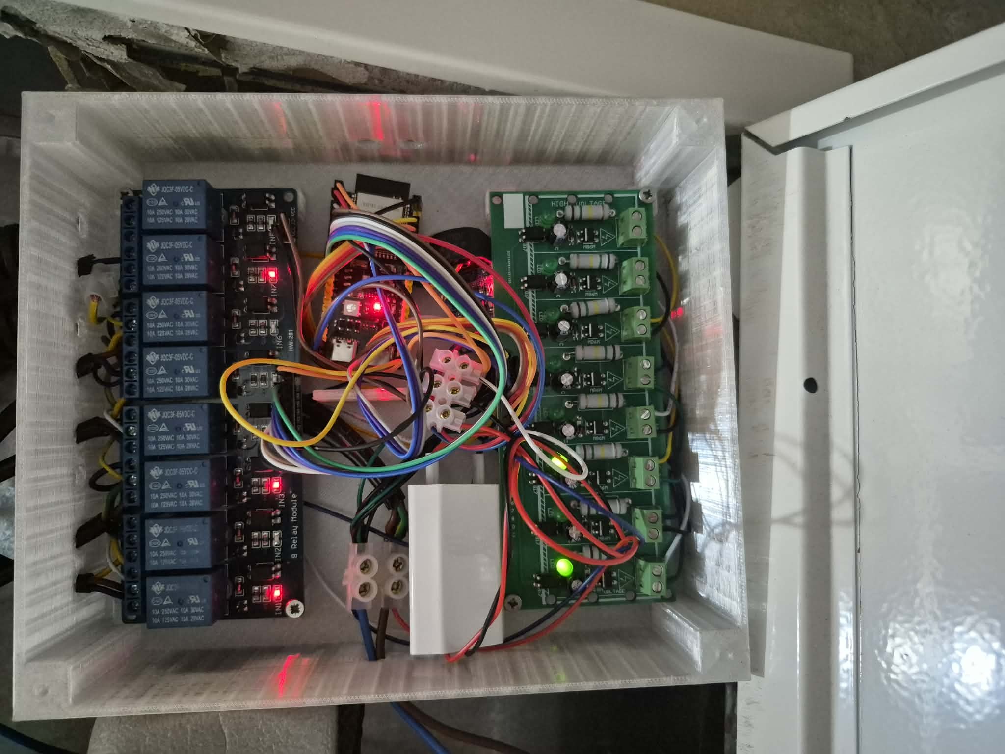
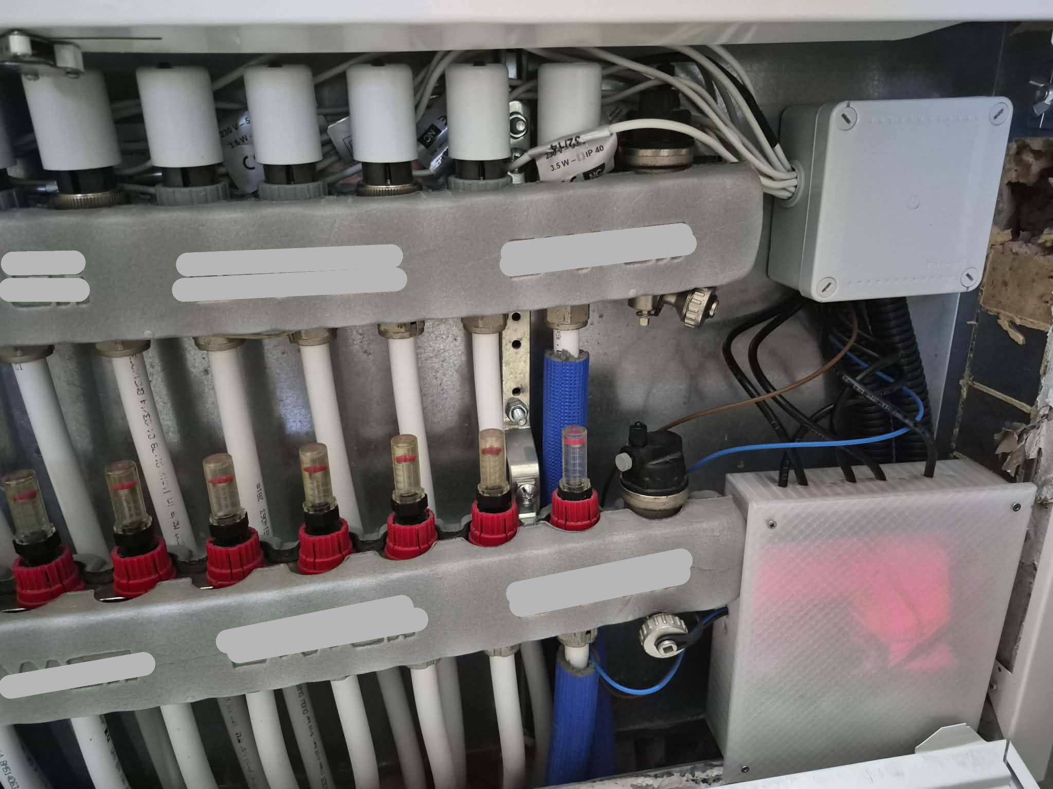
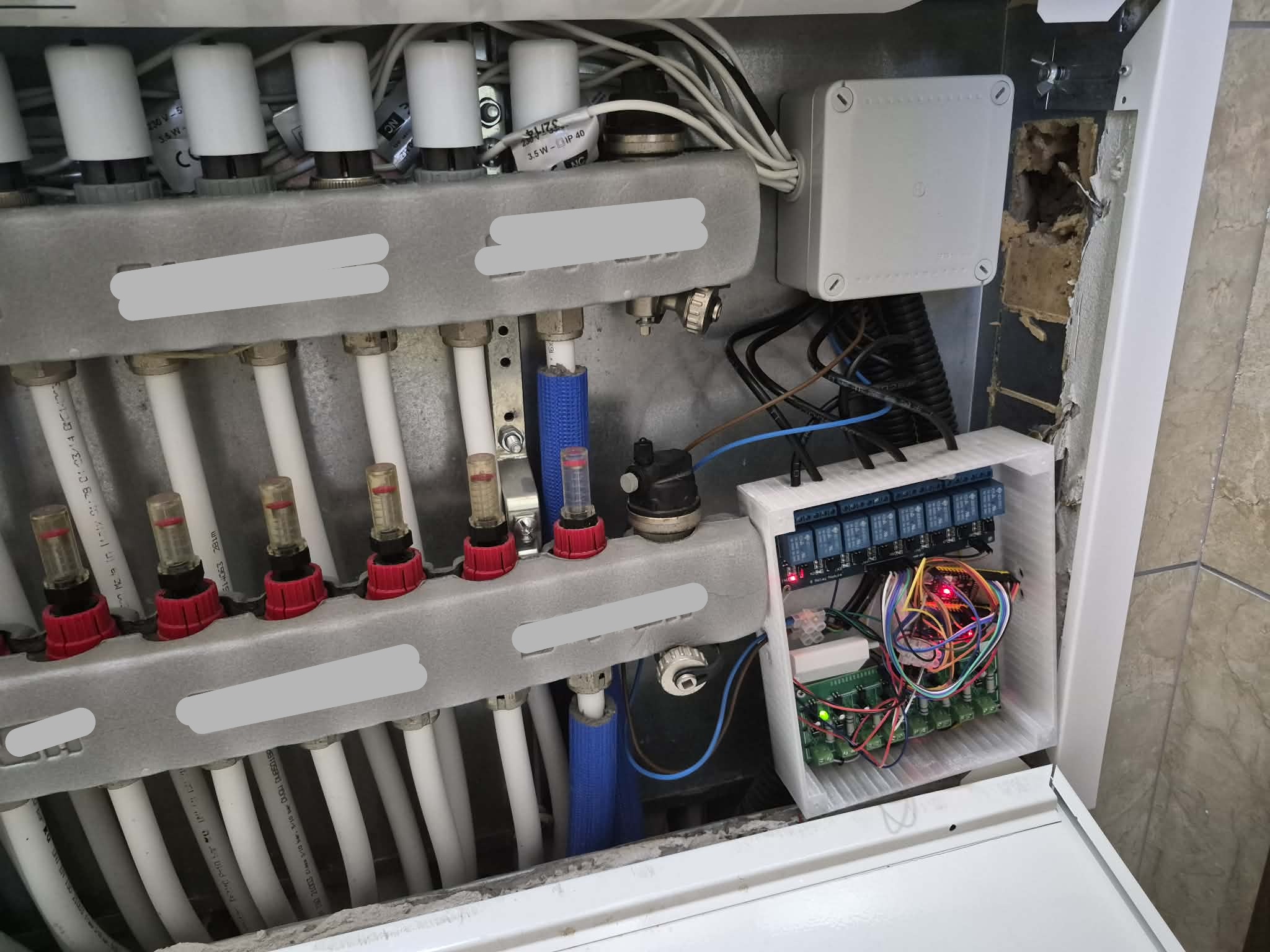
The collector is the brain of the centralized system. It is an ESP32-C6 (S3, C3 or other ESP32 models also work) that receives commands from thermostats via ESP-NOW and activates the valves and the circulator. Each collector serves a group of rooms and zones: some rooms have one valve, others have more than one.
Required components
- ESP32-C6 board (or S3/C3): collector brain
- Relay module (4+ channels): one relay per valve + one relay for the circulator
- Optocouplers: one optocoupler per valve, provides status feedback
- Charger/Power supply: one or more, converts 220V to 5V for ESP32 and relays
Power supply
The system operates at two voltage levels:
- 220V → enters the charger, which converts to 5V to power the ESP32 and relay boards
- 3.3V → powers the optocouplers and relay signals
AC side (220V): optocouplers connect to neutral.
Relay → valve connections
Each relay has three terminals:
- COM (common): connected to the valve and the optocoupler
- NC (normally closed): connected to the old thermostat, which can continue to work as backup
- NO (normally open): connected to 220V (or the valve's voltage, if different)
When the relay activates, the circuit switches from NC to NO: the old thermostat disconnects and the valve receives power from the new supply. When the relay returns to rest, the circuit switches back to NC and the old thermostat resumes control.
Optocoupler → feedback connection
The optocoupler connects to the relay's COM. When the relay activates and the valve receives power, the optocoupler detects it and sends a confirmation signal to the ESP32. This way the collector knows the valve has actually opened.
If the relay is active but the optocoupler does not confirm, the collector reports an error (the relay may be faulty or the valve stuck).
Circulator relay
The circulator has a dedicated relay. Unlike the valves, only COM and NO are used here: when the relay activates, the circuit closes and the circulator starts. The collector manages a startup delay (waits until at least one valve is open) and a delayed shutdown (after the last valve closes).
Safety logic
- Zone timeout: each valve has a maximum open time limit (2 hours). If a thermostat stops communicating (e.g. disconnects), the collector turns off the valve after the timeout to prevent it from staying on uncontrolled. If the thermostat comes back online and requests to turn on again, the collector does it immediately.
- Coherence check: every 2 minutes the collector verifies that the relay state matches the optocoupler feedback. If there is a discrepancy, it reports an error.
- Circulator alarm: if the circulator doesn't start despite the request, the collector sends an alarm to all thermostats.
Common troubleshooting
ESP32 brownouts and reboots
If the ESP32 reboots when relays activate (especially with multiple valves simultaneously), the problem is almost always the power supply. The current spike drawn by the relay coils drops the voltage below 3V and the ESP32 reboots on its own (brownout).
Solution: buffer capacitors on the 5V power supply:
| Type | Value | Use |
|---|---|---|
| Electrolytic | 470µF | General buffer, absorbs relay current spikes |
| Electrolytic | 1000µF | For systems with 4+ relays, greater buffer capacity |
| Ceramic | 100nF (0.1µF) | Filters high-frequency noise, placed near ESP32 power pins |
Connection: capacitors go between 5V and GND, as close to the ESP32 as possible. The ceramic goes directly on the board's VIN/GND pins, the larger electrolytic on the power rail.
Important note: the ceramic capacitor (100nF) does NOT replace the electrolytic and vice versa. The electrolytic handles large spikes (relays), the ceramic filters fine noise. Use them together.
Optocouplers not confirming
If the relay is active but feedback doesn't arrive:
- Check that the optocoupler is connected to the correct relay's COM
- Verify the feedback GPIO isn't already used for something else
- Measure with a multimeter if the opto pin changes state when the relay activates
Valves not opening
- Verify the relay is actually active (LED on the relay board)
- Check the wire from the valve to the relay is properly connected
- Measure voltage at the valve terminals: should be ~220V when relay is active
- Check the valve isn't mechanically stuck (try manually actuating it)
Circulator not starting
- Verify the circulator relay is active
- Check the startup delay (circulator starts only after at least one valve is open)
- Ensure the output voltage is correct
Materials and wiring
- 1.5mm² wire for 220V power supply (L and N)
- AWG24 or AWG20 wire for relay COM, NO and NC
- Terminal blocks for fixed junctions
- Crimp connectors for quick connections
- Snap connectors for solderless connections
220V Section
Mains power
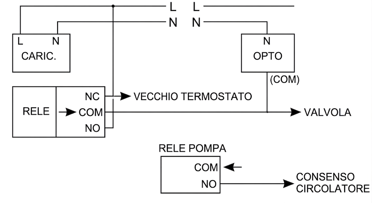
Domestic 220V mains enters the charger through the L (live) and N (neutral) lines. The charger converts 220V to 5V to power the ESP32 and relay boards.
Valve relays
Each valve is controlled by a three-terminal relay:
- NO → connected to live (L) at 220V
- COM → connected to the valve and the optocoupler
- NC → connected to the old thermostat (manual fallback)
When the relay activates, the circuit switches from NC to NO: the valve receives power and opens. When it returns to rest, the old thermostat resumes control.
Note: This guide describes a 220V AC system. For systems with different voltage or DC current, the connections must be modified according to the specifications of the valves and power supply used.
Circulator relay
The circulator has a dedicated relay with only COM and NO:
- COM → input from the circulator
- NO → circulator consensus output
When the relay activates, the circulator starts. The collector manages a startup delay and delayed shutdown.
Optocouplers
Each optocoupler monitors the state of the corresponding relay:
- N → neutral (shared with the charger)
- COM → connected to the relay's COM
When the relay activates, the opto detects it and sends feedback to the ESP32.
220V electrical schematic
Low Voltage Section
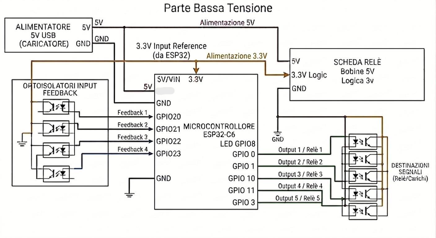
5V power supply
The charger provides 5V that powers:
- ESP32-C6 → through the VIN or 5V pin on the board
- Relay board → relays receive 5V for the coils
The charger's GND must be connected to the ESP32 and relay board GND.
3.3V power supply
The ESP32 provides 3.3V from the dedicated pin. This voltage powers:
- Optocouplers → each opto receives 3.3V for the digital side
- Relay signals → relay pins operate at 3.3V
GND is common to the entire system.
ESP32 → Relay connections
Each relay is controlled by an OUTPUT GPIO pin on the ESP32. When the GPIO goes high (3.3V), the relay activates.
| Zone | Relay Pin |
|---|---|
| 1 | GPIO0 |
| 2 | GPIO1 |
| 3 | GPIO10 |
| 4 | GPIO11 |
| Circulator | GPIO3 |
| LED | GPIO8 |
Optocouplers → ESP32 connections
Each optocoupler provides feedback on the corresponding relay state through an INPUT GPIO pin. When the relay activates and the opto detects current, it sends a signal to the ESP32 GPIO.
| Zone | Feedback Pin |
|---|---|
| 1 | GPIO20 |
| 2 | GPIO21 |
| 3 | GPIO22 |
| 4 | GPIO23 |
Optocoupler → relay connections (AC side)
The AC side of the optocoupler connects to the corresponding relay's COM. This allows the opto to detect when the relay is active and the valve is receiving power.
Low voltage schematic
Notes
- ⚠️ Safety: the collector contains mains voltage (230V). Always work with power disconnected, use insulated materials and verify connections before reconnecting power. Do not expose the device to humidity or accidental contact.
- Disclaimer: this tutorial is for informational and educational purposes only. It is not an industrial product, but a handmade device, built and used without any warranty. Anyone performing the assembly does so at their own risk and assumes responsibility for any damage to people or property resulting from the use of the device.
- Reference: this tutorial is part of the official documentation CLIMAORO on GitHub.
📋 Thermostat assembly tutorial:
Build configuration: