Thermostat Assembly
Building the CLIMAORO thermostat: an ESP32 board powered by a recycled USB phone charger, connected to an SHT40 temperature/humidity sensor and placed inside a 3D printed case in place of the old wall thermostat.
⚠️ DANGER – MAINS VOLTAGE (230V). This build is connected to the mains: contact with the voltage can cause dangerous electric shocks. Disconnect the power before any intervention. Never touch the internal components while the device is powered. If you are not experienced with electricity, have a qualified electrician do the installation.
3D printing the case
The thermostat case is 3D printed. The model is the same one used for the mobile thermostat:
- File: termostato-ovale-19-c6.3mf
- Recommended material: PETG
- Note: the file can only be opened with OrcaSlicer or Flash Studio
⚠️ Disclaimer: the 3D model is provided as-is, for educational and experimental purposes. Tolerances may vary depending on printer, material and calibration. Not certified for production use.
Assembly steps
Required materials
| Material | Use |
|---|---|
| ESP32 (C3 or C6) | Thermostat brain |
| USB phone charger (5V) | Power supply (recycled) |
| SHT40 sensor (temperature/humidity) | Temperature measurement |
| 3D printed case | Houses PCB, ESP32 and sensor |
| Small screwdriver | Opening the charger |
| Soldering iron + solder | Electrical connections |
| Wire (red, white, green, yellow, black) | Wiring |
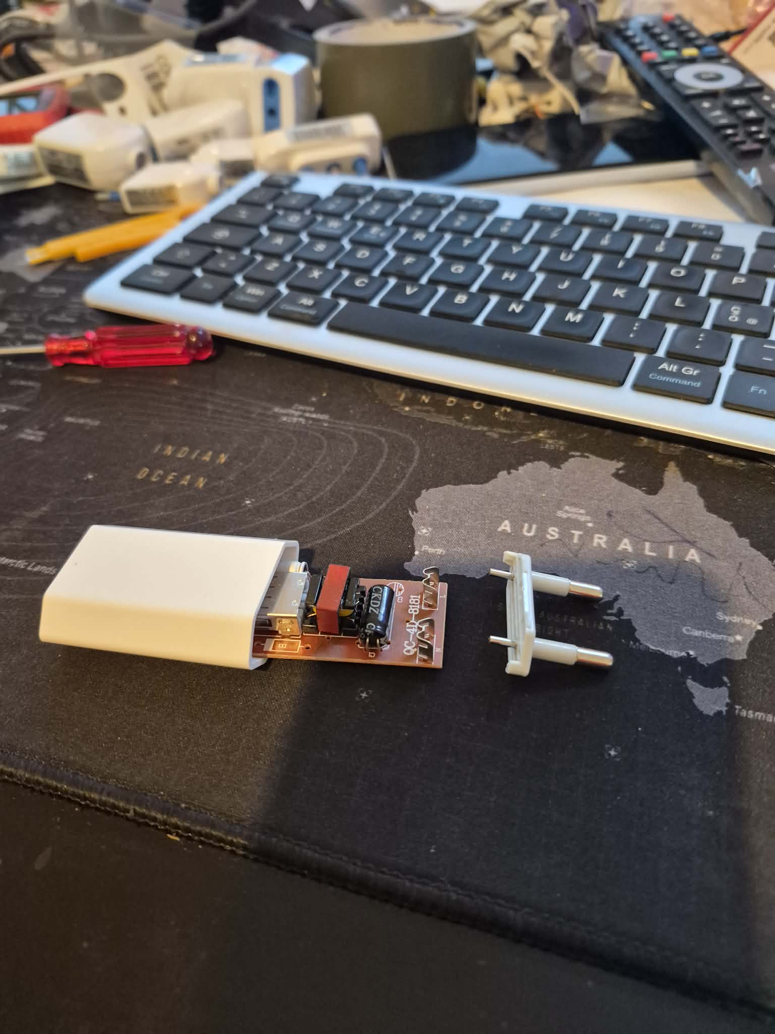
1. Open the charger
With a small screwdriver, open the case of the USB phone charger. From the charger you need two parts:
- the two metal prongs (the male contacts that plug into the wall socket, where the 230V passes through);
- the PCB (the internal board), from which you will take the 5V to power the ESP32.
The charger's plastic case is not used instead: the components will be housed in the 3D printed case.
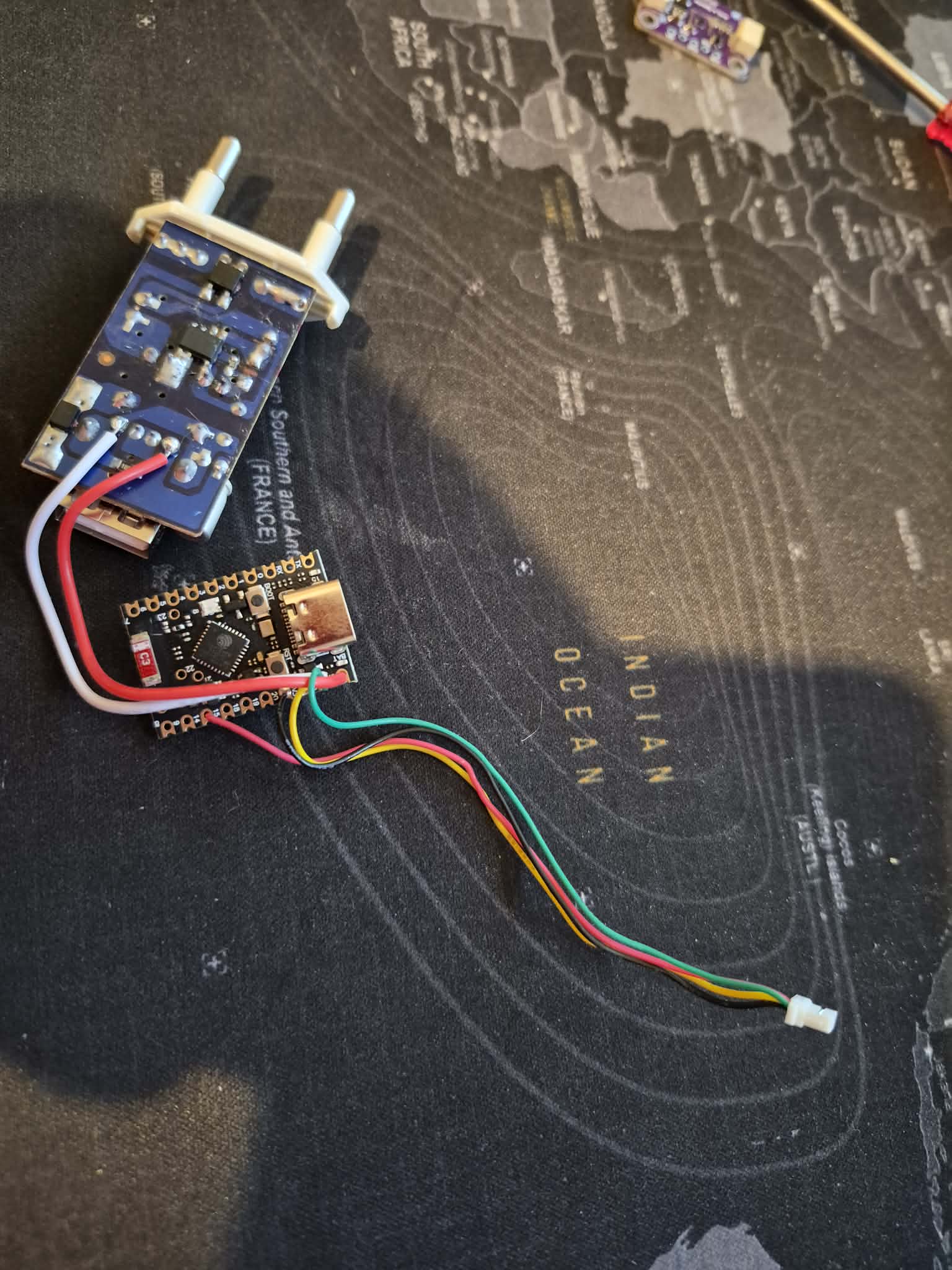
2. Solder the connections
When soldering is complete, the circuit will look like this:
                    ┌─────────────────┐
 USB CHARGER ──────>│    ESP32        │
   (5V from PCB)    │                 │
   VCC (red) ───────> 5V / VIN        │
   GND (white) ─────> GND             │
                    │                 │
 SHT40 SENSOR ─────>│                 │
   VCC (yellow) ────> 3V3             │
   GND (green) ─────> GND             │
   SDA (black) ─────> SDA (i2c pin)   │
   SCL (red) ───────> SCL (i2c pin)   │
                    └─────────────────┘
On the charger PCB, solder the VCC (red) wire and the GND (white) wire. Also solder the electrical prongs that will plug into the base of the wall thermostat (they carry the 230V supply to the charger).
On the ESP32, solder the two charger wires (power supply) and the four sensor wires:
- GND (green) → GND pin
- VCC (yellow) → 3V3 pin
- SDA (black) → SDA pin
- SCL (red) → SCL pin
Note: the SDA/SCL pins depend on the ESP32 model and are defined in the ESPHome configuration file (
i2c_sda/i2c_scl): - ESP32-C6 → SDA 20, SCL 14 - ESP32-C3 → SDA 0, SCL 1
Always check the pins in your YAML file before soldering.
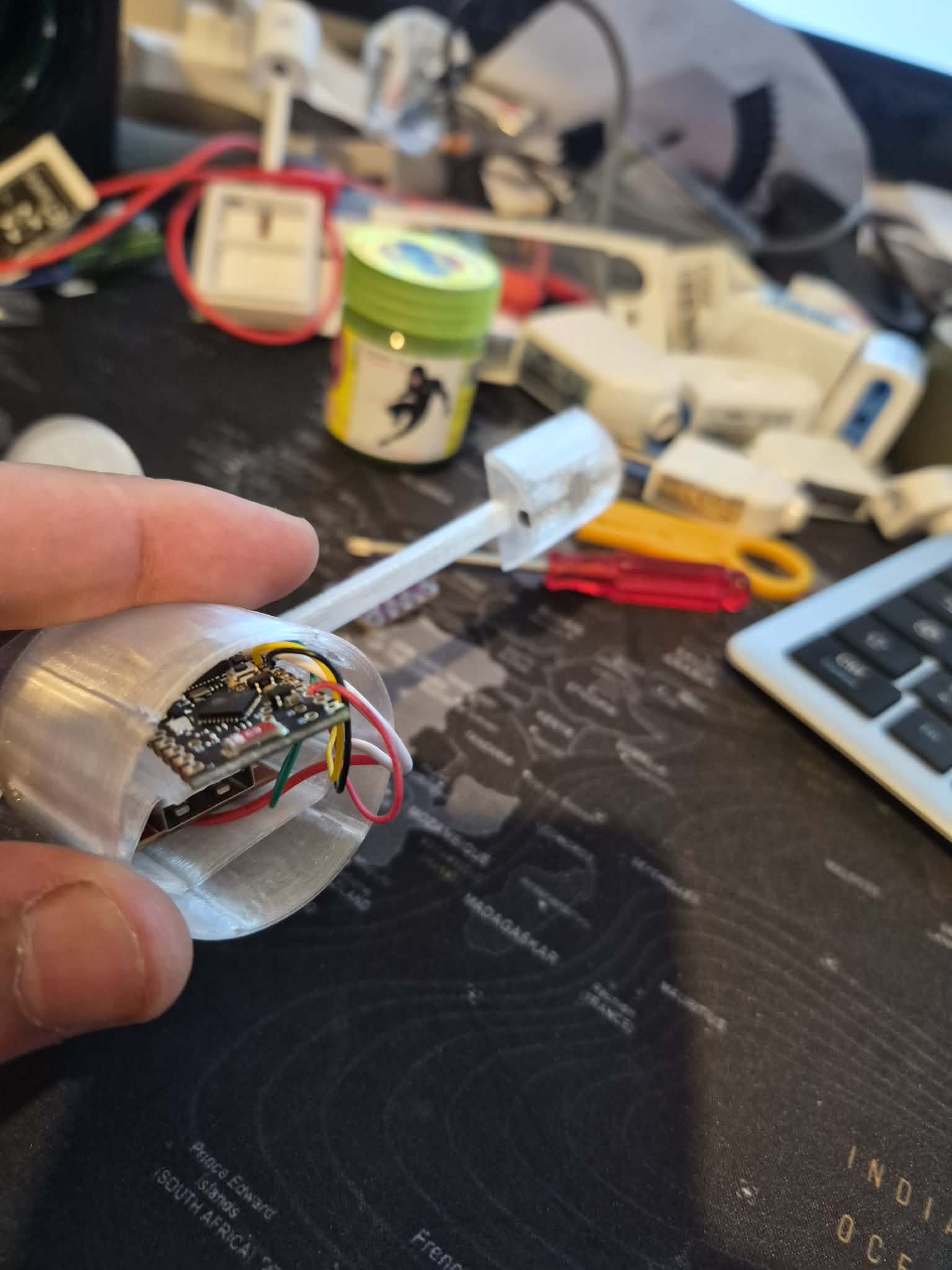
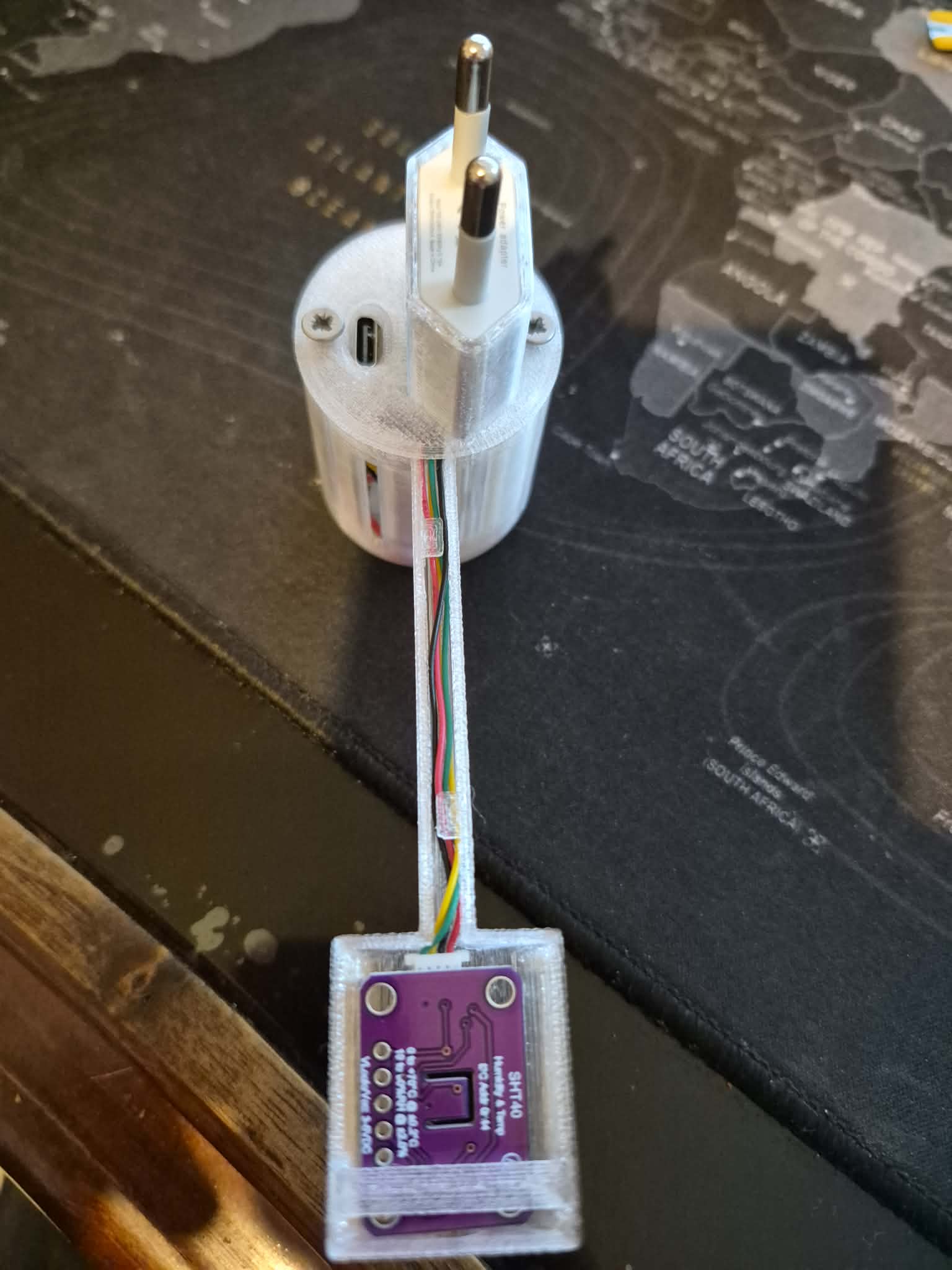
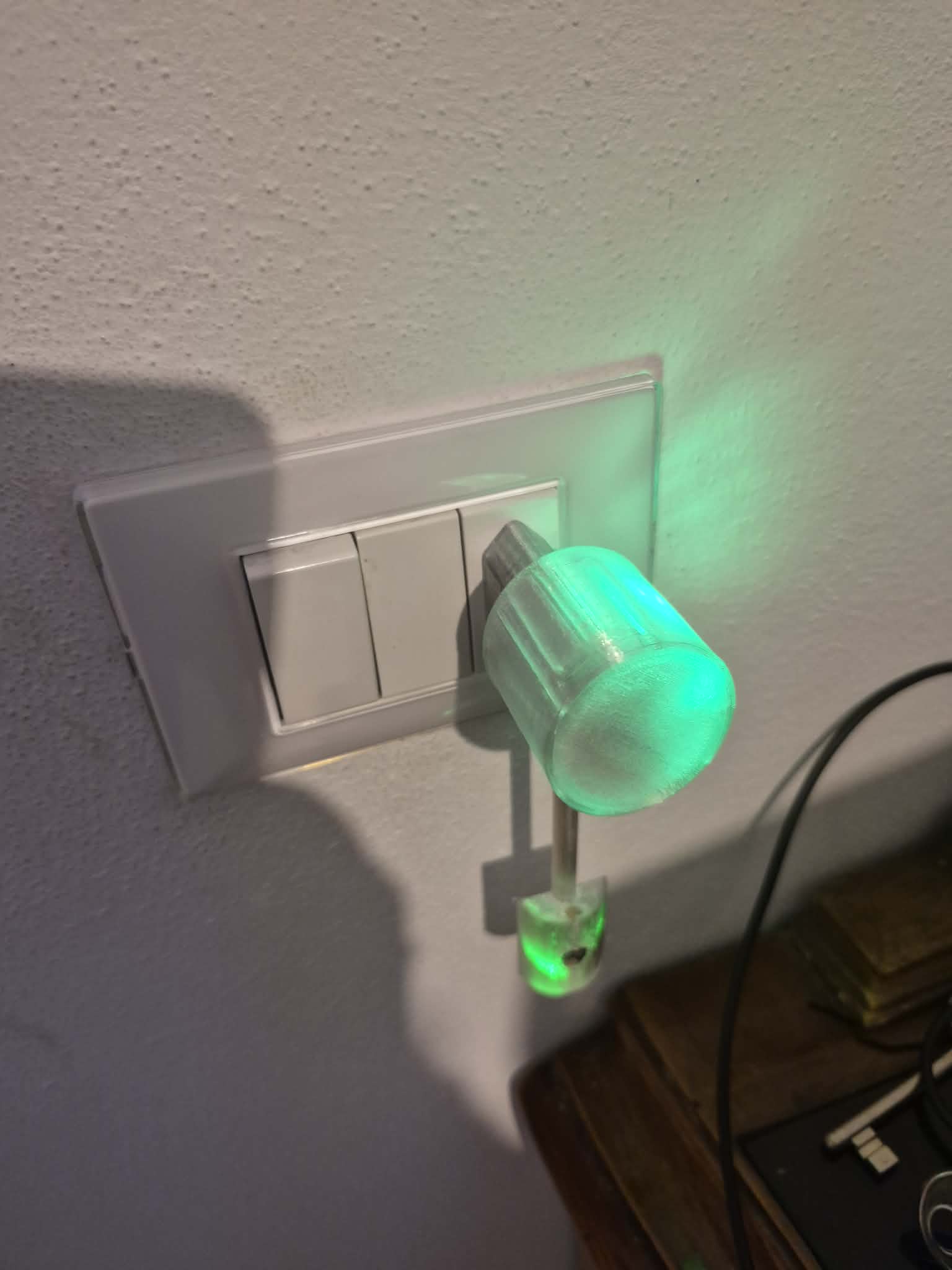
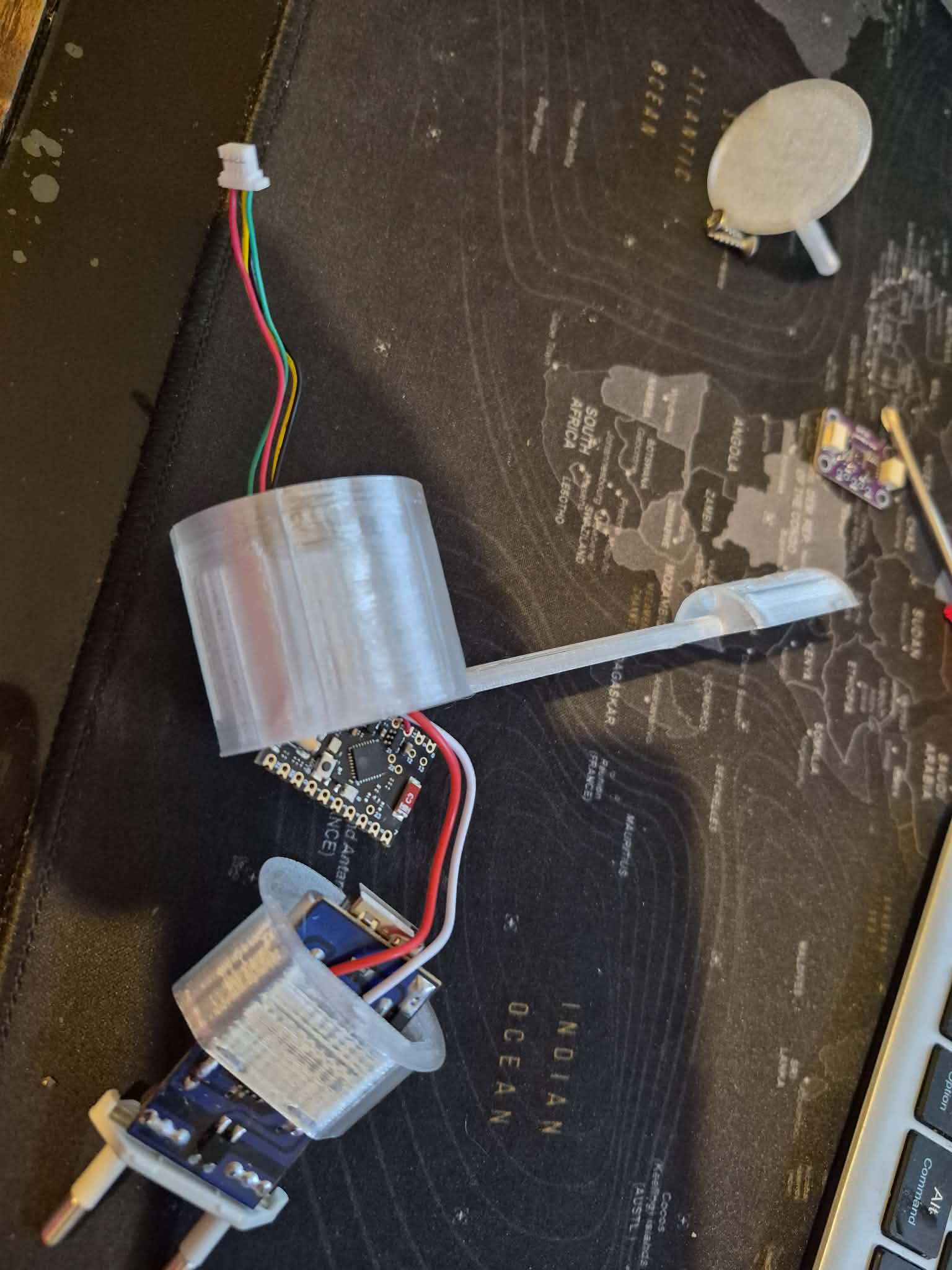
3. Insert the components into the 3D case
Insert the following in this order into the 3D printed case, where the prongs will act as a lock:
- the bundle of wires (the cables going outside)
- the ESP32
- the charger PCB with the soldered prongs, which will close the thermostat plug
4. Position the ESP32 and the sensor
Insert the ESP32 into the case housing and route the sensor wires towards the bottom.
5. Close the lid
Insert the thermostat lid with the slender leg on the side opposite the ESP32: that space is the tightest, while the other leg fits with some effort. Close everything with two screws. Connect the sensor to the four wires and insert it into its dedicated housing.
Final check
- Reconnect the power.
- The thermostat should appear online in Home Assistant (via ESPHome/API).
- Check that the sensor publishes temperature and humidity.
- If it does not appear: recheck the solder joints (especially SDA/SCL and the power connections) and the charger voltage.
Troubleshooting
Thermostat keeps rebooting
If the ESP32 reboots when Wi-Fi connects or when communicating with the collector, the problem is almost always the power supply. Old or low-quality USB chargers can't handle the current spikes.
Solution: add a 470µF electrolytic capacitor between 5V and GND, as close to the ESP32 power pins as possible. The capacitor absorbs current spikes and stabilizes the voltage.
Connect it between the VIN (or 5V) and GND pins of the ESP32, with the positive terminal (+) on 5V and the negative terminal (-) on GND.
Notes
- ⚠️ Safety: the build contains mains voltage (230V) inside the charger. Always work with the power disconnected, use insulating materials and check the connections before reconnecting the power. Do not expose the device to moisture or accidental contact.
- Responsibility: this tutorial is for informational and educational purposes. This is not an industrial product, but an artisanal device, built and used without any warranty. Whoever performs the assembly does so at their own risk and assumes responsibility for damage to people or property resulting from the use of the device.
- Upcycling: the USB charger is a recycled component: it just needs to provide stable 5V and at least ~1A.
- Reference: this tutorial is part of the official CLIMAORO documentation on GitHub.